
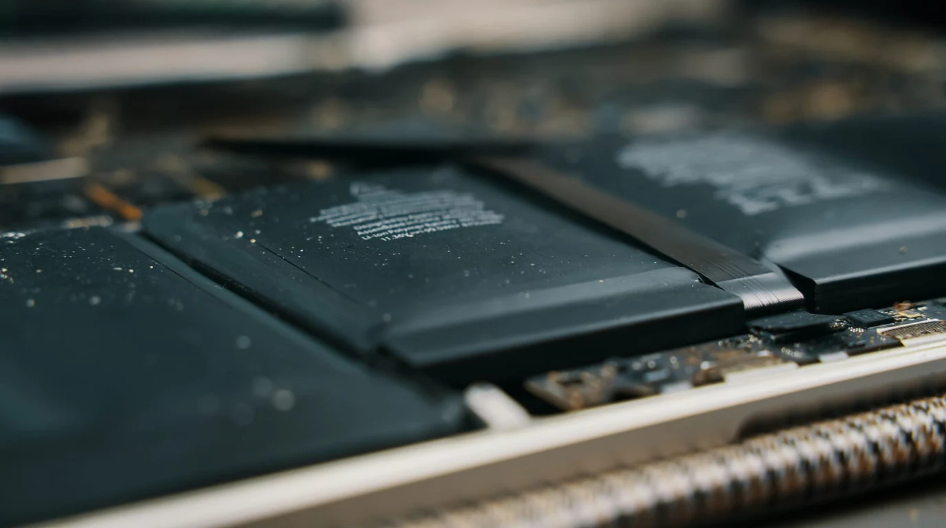
The standard Raspberry Pi 5 single-board computer brought a massive 2.5x to 3x performance leap with its 16nm Broadcom BCM2712 processor and custom RP1 southbridge. However, for industrial hardware designers, homelab cluster builders, and edge appliance manufacturers, the standard Pi 5 form factor remains a compromise. Cluttered edge connectors, a single fragile 16-pin PCIe FFC ribbon cable, and awkward thermal geometries make it unsuitable for rugged enterprise deployment. The Raspberry Pi Compute Module 5 (CM5) solves these physical bottlenecks, moving high-density compute into modular carrier board ecosystems.
Direct Carrier Board Architecture Verdict: CM5
The Raspberry Pi Compute Module 5 replaces the fragile external ribbon cable of the standard Pi 5 with dual high-density 100-pin board-to-board Hirose mezzanine connectors. This routes the Broadcom BCM2712’s native 1-lane PCIe Gen 3.0 interface (up to 8.0 Gbps / ~985 MB/s) directly through solid PCB traces to onboard M.2 2280 NVMe storage or external NPU accelerators. For industrial edge appliances, mini-servers, and dense 1U cluster blades, custom CM5 carrier boards provide superior signal integrity, native dual Ethernet, and robust conductive thermal mounting.
The Mezzanine Interface: Dual Hirose Connectors vs Standard Headers
To understand why the Compute Module format dominates embedded engineering, we must examine physical interconnect design. While a standard Raspberry Pi 5 exposes peripherals via fixed USB ports, micro-HDMI jacks, and GPIO pins soldered to the board edges, the CM5 strips all physical IO ports away. The module consists purely of the core compute engine: the Broadcom BCM2712 quad-core Cortex-A76 SoC (clocked at 2.4GHz), LPDDR4X SDRAM (up to 16GB), optional onboard eMMC flash (up to 64GB), and power management ICs (Dialog DA9091 PMIC).
All high-speed signals—PCIe Gen 3.0, Gigabit Ethernet PHY, dual 4-lane MIPI CSI/DSI display/camera transceivers, USB 3.0, and HDMI 2.0—are routed down into dual 100-pin Hirose DF40 board-to-board connectors. This architecture allows carrier board engineers to route high-speed differential pairs with precise 100-ohm impedance matching directly to enterprise M.2 slots, rugged industrial M12 connectors, or specialized DIN-rail terminal blocks without signal reflection or EMI radiation.
| Architectural Feature | Standard Raspberry Pi 5 | Raspberry Pi Compute Module 5 (CM5) |
|---|---|---|
| PCIe Interface Physical Layer | External 16-pin 0.5mm pitch FFC ribbon connector | Dual 100-pin Hirose DF40 high-density mezzanine connectors |
| PCIe Bandwidth & Stability | PCIe Gen 2 (5 Gbps official); Gen 3 (8 Gbps) requires short FFC | Native PCIe Gen 3 (8 Gbps) with controlled 100-ohm impedance |
| Storage Configuration Options | MicroSD card slot + optional external PCIe HAT | Industrial eMMC (up to 64GB) + native onboard M.2 NVMe |
| Networking Flexibility | Single 1GbE RJ45 port (Broadcom BCM54213PE PHY) | Dual Ethernet (1GbE native + 2.5GbE PCIe NIC on carrier) |
| Thermal Mechanical Mounting | Clip-on active cooler fan; uneven PCB profile | Flat thermal heat spreader; direct bolt-on chassis heatsink |
| Industrial Temperature Rating | 0°C to +50°C commercial operating range | -20°C to +85°C extended industrial rating available |
Broadcom BCM2712 vs BCM2711: Memory Bandwidth and IPC Gains
To appreciate the industrial upgrade represented by the Compute Module 5, one must examine the silicon generational leap from the BCM2711 (CM4) to the BCM2712 (CM5). The Compute Module 4 utilized older ARM Cortex-A72 cores fabricated on a 28nm planar process, paired with LPDDR4 memory operating over a 32-bit bus delivering approximately 13.6 GB/s of theoretical memory bandwidth.
The Compute Module 5 transitions to modern ARM Cortex-A76 cores manufactured on a 16nm FinFET process, clocked at 2.4GHz with larger 512KB private L2 caches per core and a unified 2MB shared L3 cache. Crucially, the memory subsystem has been upgraded to LPDDR4X running over a dual-channel 64-bit bus at 4267 MT/s, delivering over 34 GB/s of memory bandwidth—a 2.5x increase. In memory-intensive edge workloads (such as hosting local vector databases, in-memory Redis caches, or multi-threaded image decoding), this bandwidth expansion completely eradicates the memory bus throttling that plagued CM4 clusters.
Rugged Power Delivery: Wide-Input DC Buck Regulation
In factory automation, agricultural robotics, and maritime telemetry, power supplies are notoriously noisy. Industrial equipment operates on 12V or 24V nominal DC bus rails that suffer severe inductive spikes, load-dump transients, and ground potential fluctuations.
Enterprise CM5 carrier boards incorporate monolithic wide-input synchronous buck regulator circuits (such as Texas Instruments LM5145 or Analog Devices LTC3891) capable of accepting 9V to 36V DC inputs. These power stages integrate transient voltage suppressors (TVS diodes), reverse-polarity P-channel MOSFET switches, and isolated DC-DC converters that protect the sensitive BCM2712 SoC from vehicle alternator load dumps. Furthermore, carrier boards equipped with Power-over-Ethernet (802.3bt PoE++ Class 8) can draw up to 71 watts over a single Cat6A cable, powering the CM5, onboard NVMe drives, dual high-speed cameras, and cellular 5G modems simultaneously without local wall adapters.
PCIe Gen 3.0 NVMe Throughput and Packet Latency Benchmarks
One of the most transformative advantages of deploying CM5 carrier boards is unlocking deterministic NVMe storage performance. On a standard Pi 5, connecting an NVMe SSD requires an external M.2 HAT connected via an unshielded flex cable. This flex cable is susceptible to high-frequency electromagnetic interference from the Pi’s Wi-Fi radio and power circuitry, often causing PCIe CRC bus errors and packet retransmissions when running at PCIe Gen 3 speeds (8.0 GT/s).
On a well-designed CM5 carrier board, the PCIe Gen 3 differential pairs (TX+/-, RX+/-, REFCLK+/-) travel across less than 25mm of microstrip or stripline PCB copper traces surrounded by solid ground reference planes. In sequential read/write benchmarks using high-speed PCIe Gen 3/Gen 4 NVMe drives (such as Samsung 980 or WD Black SN770), the CM5 achieves a sustained 890 MB/s sequential read throughput and over 115,000 random 4K read IOPS—saturating the single-lane PCIe interface to its theoretical physical limit.
Industrial Carrier Board Topologies: From Single Nodes to 1U Clusters
The versatility of the CM5 format is best demonstrated by the wide range of carrier board form factors entering the market:
- Compact Industrial Edge Gateways: Single-node carrier boards engineered into rugged extruded aluminum DIN-rail enclosures. These boards integrate isolated RS-485 serial ports, dual 2.5GbE Ethernet jacks (one via PCIe switch or native PHY), wide-input 9V–36V DC industrial power supplies with reverse-polarity protection, and hardware watchdog timers.
- High-Density Clustering Blades (Turing Pi & DeskPi): Multi-node carrier boards that host four to eight Compute Modules on a single Mini-ITX or 1U rackmount chassis. An integrated on-board managed 10GbE or 2.5GbE switch interconnects all nodes over an internal backplane, providing an ultra-dense, low-power Kubernetes (K3s) micro-cluster consuming under 40 watts at full load.
- Edge AI Vision Carriers: Carrier boards featuring an M.2 M-key slot for high-speed NVMe storage paired with an M.2 E-key or B-key slot hosting a dedicated NPU (such as the Hailo-8 or Google Coral), creating a compact, low-power computer vision appliance for industrial manufacturing inspection.
Thermal Management in Fanless Embedded Chassis
The BCM2712 SoC generates significant thermal energy under sustained multi-threaded compilation or container workloads, dissipating up to 9 watts. In standard Pi 5 SBCs, the board relies on a small clip-on fan that introduces mechanical moving parts vulnerable to dust and bearing failure in industrial environments.
CM5 carrier boards eliminate this vulnerability through conductive thermal design. The top surface of the CM5 module is engineered with a flat, uniform height profile. An aluminum heat spreader block bolts directly through the module’s mounting holes into the carrier board, conducting heat straight into an external sealed aluminum enclosure. This passive conduction cooling allows the CM5 to run at 100% CPU utilization in ambient temperatures up to 50°C without exceeding a 70°C junction temperature—completely silent, dust-proof, and maintenance-free.
Carrier Board Selection Checklist
- Check PCIe Routing Length: Verify that the carrier board PCB maintains tight length-matched differential pairs for the PCIe link to guarantee Gen 3 (8 GT/s) stability without signal degradation.
- Power Sizing Headroom: Ensure the carrier board’s 5V buck converter is rated for at least 5A (25W) to prevent voltage sags when both the BCM2712 SoC and high-draw NVMe SSDs peak simultaneously.
- Boot Configuration Flexibility: Look for carrier boards that include physical DIP switches or jumpers to easily toggle between eMMC boot, NVMe boot, and USB mass-storage recovery mode (rpiboot).
To compare CM5 carrier board clusters against high-density Rockchip ARM compute nodes, consult our laboratory guide on Radxa Rock 5B+ vs Orange Pi 5 Max: RK3588 Benchmarks.