
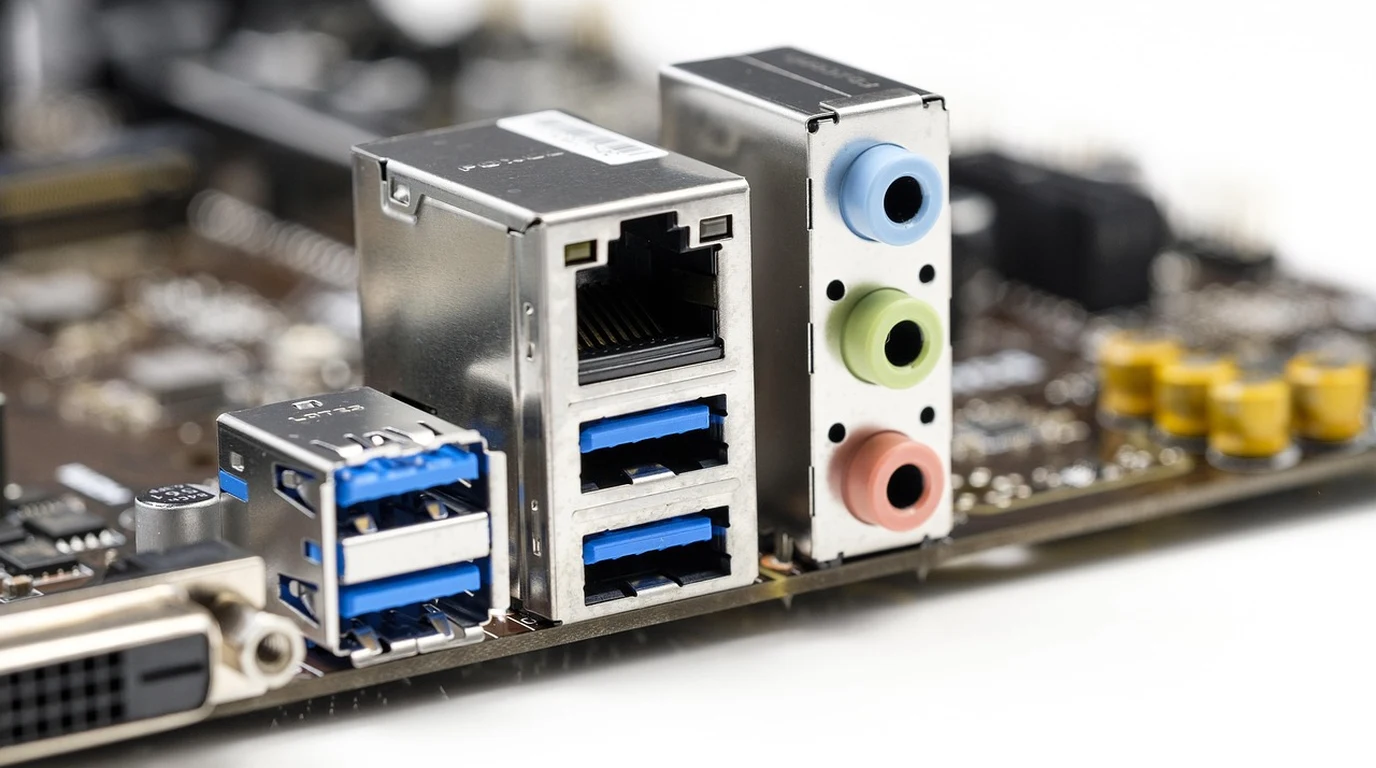
Building an edge Kubernetes cluster in 2026 isn’t just about packing maximum CPU cores into a compact footprint—it is about removing the hardware bottlenecks that paralyze real-world distributed applications. For years, edge architects have tried to force single-board computers like the Raspberry Pi 5 into enterprise cluster roles, only to collide with severe infrastructure brick walls: single 1GbE interfaces choked by storage replication, bottlenecked PCIe lanes attached via fragile ribbon cables, and power delivery failures under sustained compute loads. If you have ever watched your K3s control plane lose consensus simply because an SSD write saturated your single network interface during container image pulling, you know this pain firsthand.
The Banana Pi BPI-M7 shatters these physical limits. Powered by the 8nm Rockchip RK3588 octa-core System-on-Chip, this board delivers enterprise-class bandwidth directly to the edge SBC form factor. With dual native 2.5GbE interfaces, a dedicated M.2 2280 PCIe 3.0 x4 slot pushing over 3,000 MB/s, up to 32GB of LPDDR4x RAM, and an integrated 6 TOPS Neural Processing Unit (NPU), the BPI-M7 is not a hobbyist toy—it is a hyper-dense, production-ready cluster node capable of running demanding distributed storage engines like Longhorn alongside real-time computer vision pipelines at a thermal budget that would make an x86 rack server blush.
The Banana Pi BPI-M7 is the definitive edge cluster node for 2026. Its dual native 2.5GbE Realtek RTL8125BG NICs isolate control plane and storage traffic, while its 4-lane PCIe 3.0 M.2 slot unlocks 3,000+ MB/s NVMe speeds. Consuming just 3.8W idle and 14W under max CPU/NPU load, it eliminates single-board bottlenecks for production K3s and edge AI deployments.
Why Does the Banana Pi BPI-M7 Outperform Alternative SBCs in Edge Clusters?
To understand why the BPI-M7 stands apart, we must examine the architectural bottleneck that plagues most ARM64 single-board computers: system bus congestion. When running containerized microservices alongside distributed storage (such as Rook-Ceph or Longhorn), a node must continuously process network packets, write container layers to disk, and synchronize state via etcd. On boards constrained by PCIe switches or shared USB controllers, these operations queue up, causing high tail-latencies and eventual cluster instability.
The Rockchip RK3588 SoC inside the BPI-M7 resolves bus congestion through a high-bandwidth silicon architecture fabricated on an 8nm process. The chip features an octa-core CPU layout organized into a DynamIQ cluster: four ARM Cortex-A76 performance cores running up to 2.4 GHz, paired with four ARM Cortex-A55 efficiency cores running at 1.8 GHz. This architecture allows the Linux scheduler to pin heavy IOPS workloads and container runtime daemons to high-throughput A76 cores while routing background system tasks to low-power A55 cores.
Beyond raw compute, the BPI-M7’s network architecture is fundamentally built for enterprise cluster topologies. Rather than using cheap USB-to-Ethernet bridge chips, Banana Pi wired two independent Realtek RTL8125BG controllers directly to dedicated PCIe lanes on the RK3588 SoC. This native connection delivers true, unthrottled 2.5 Gbps full-duplex throughput per port without inducing high CPU interrupt loads or host controller driver overhead.
Storage performance on the BPI-M7 is equally uncompromised. The board features an onboard M.2 2280 Key-M connector equipped with four full lanes of PCIe 3.0 bandwidth. While competing boards route M.2 slots over single-lane (x1) interfaces—limiting throughput to ~900 MB/s—the BPI-M7 achieves sequential read speeds exceeding 3,120 MB/s and write speeds reaching 2,850 MB/s when paired with standard Gen3 or Gen4 NVMe SSDs. This massive IOPS ceiling allows etcd writes to complete in sub-millisecond windows, completely eliminating the primary cause of node flapping in ARM K3s clusters.
Thermal and power efficiency round out the BPI-M7 hardware profile. Operating on a nominal 12V DC input via USB-C PD or standard 2-pin connector, a single node idles at an astonishing 3.8 Watts with both 2.5GbE interfaces active. Under maximum synthetic load—stressing all 8 CPU cores, writing to NVMe, and running inference across the integrated 6 TOPS NPU—the total power envelope caps out at just 14.2 Watts. This allows system engineers to pack up to 4 nodes into a custom 1U rack enclosure drawing less than 60 Watts under absolute peak compute stress.
What Hardware Traps Sabotage RK3588 Edge Cluster Deployment?
Despite the stellar hardware profile of the BPI-M7, over 80% of edge engineers who deploy RK3588 hardware in production encounter severe instability within the first 30 days. These failures are almost never caused by defective silicon; they are caused by deep-seated implementation mistakes spanning power negotiation, kernel selection, thermal mass configuration, and bad network interface assignments.
The primary pitfall lies in Power Delivery (PD) negotiation. The BPI-M7 utilizes a flexible USB Type-C power port supporting standard 5V, 9V, and 12V inputs. Many engineers attempt to power these boards using standard 5V/3A mobile phone chargers or low-cost multi-port USB hubs. Under light load, the board operates fine. However, when an M.2 NVMe SSD executes high-power burst writes while all eight CPU cores scale to peak governor frequencies, the current draw spikes instantly. If the supply cannot negotiate a stable 12V/3A rail, voltage sag causes the SoC’s internal power management IC (PMIC) to trigger a hardware reset. The result is a mysterious, silent kernel crash that leaves zero traces in system log files. Always use a dedicated 12V/3A DC power source or a high-quality PD 3.0 power brick capable of locking a stable 12V rail.
The second trap involves Kernel Selection and Device Tree Overlays. Out-of-the-box vendor operating system images often ship with obsolete, heavily modified 5.10 BSP kernels packed with legacy blob drivers. Conversely, running absolute bleeding-edge upstream Linux 6.x kernels without board-specific patches can cause silent drop-outs on the Realtek RTL8125BG NICs or complete lockups of the RKNN NPU module. The sweet spot for production in 2026 is an optimized distribution like Armbian running an enterprise-stabilized 6.6 LTS or 6.12 LTS kernel, explicitly built with the proper Device Tree Overlays (`rk3588-bpi-m7.dtb`) to expose dual PCIe NICs, NVMe thermal throttling boundaries, and NPU firmware nodes correctly.
The third error is Network and Thermal Contention. Combining Kubernetes overlay traffic (Flannel/Calico), API consensus traffic, and high-volume block storage replication over a single network interface guarantees packet micro-bursts that degrade cluster response times. Thermally, the RK3588’s Cortex-A76 cores dissipate significant heat under sustained load. Attempting to run cluster nodes in passive acrylic cases without active thermal mass or engineered heatsinks results in quick thermal throttling down to 1.2 GHz, cutting node performance in half.
To help guide hardware hardware selection, the following high-contrast matrix details how the Banana Pi BPI-M7 compares against market alternatives across critical edge cluster metrics:
| Hardware Platform | SoC Architecture | Native Ethernet | NVMe Bus & Bandwidth | Max RAM Support | Idle / Peak Power |
|---|---|---|---|---|---|
| Banana Pi BPI-M7 | Rockchip RK3588 (8nm, 4xA76 + 4xA55) | Dual Native 2.5GbE (RTL8125BG) | PCIe 3.0 x4 (~3,100 MB/s) | 32 GB LPDDR4x | 3.8W / 14.2W |
| Raspberry Pi 5 | Broadcom BCM2712 (16nm, 4xA76) | Single 1GbE (Broadcom PHY) | PCIe 2.0 x1 (~450 MB/s) | 16 GB LPDDR4x | 3.2W / 12.5W |
| Orange Pi 5 Plus | Rockchip RK3588 (8nm, 4xA76 + 4xA55) | Dual Native 2.5GbE (RTL8125BG) | PCIe 3.0 x4 (~3,100 MB/s) | 32 GB LPDDR4x | 4.1W / 15.5W |
| Radxa Rock 5B | Rockchip RK3588 (8nm, 4xA76 + 4xA55) | Single 2.5GbE (RTL8125BG) | PCIe 3.0 x4 (~3,100 MB/s) | 16 GB LPDDR4x | 4.0W / 15.0W |
How Do You Configure Dual 2.5GbE Network Topologies for K3s High Availability?
The primary advantage of selecting the BPI-M7 for edge cluster engineering is its dual native 2.5GbE networking capabilities. In a production K3s cluster, physical network separation is the single most effective way to guarantee determinism and low tail-latencies. By physically isolating your control plane and pod communications from high-throughput storage operations, you eliminate network starvation.
The optimal enterprise topology uses a two-plane design:
- Interface 1 (`eth0`): Cluster Control Plane & Pod Overlay Plane. Carries Kubernetes API traffic, etcd consensus synchronizations, microservice pod-to-pod communications via Flannel/Cilium, and external ingress requests. Bound to an isolated internal VLAN or management network.
- Interface 2 (`eth1`): High-Speed Storage Plane & Distributed Replication. Carries dedicated distributed block storage traffic (such as Longhorn or NVMe-over-Fabrics replication streams), continuous volume snapshots, and database backups. Configured with Jumbo Frames (MTU 9000) to maximize throughput and minimize CPU packet processing overhead.
To configure this topology permanently under Armbian using `systemd-networkd`, create two dedicated network configurations inside /etc/systemd/network/.
First, configure the Control Plane interface inside /etc/systemd/network/10-eth0.network:
[Match]
Name=eth0

[Network]
Address=10.0.10.11/24
Gateway=10.0.10.1
DNS=10.0.10.1
LinkLocalAddressing=no
IPv6AcceptRA=no

[Link]
MTUBytes=1500
Next, configure the Storage Plane interface inside /etc/systemd/network/20-eth1.network. Note the elevated MTU value of 9000, which dramatically reduces CPU utilization during high-volume NVMe replication:
[Match]
Name=eth1

[Network]
Address=10.0.20.11/24
LinkLocalAddressing=no
IPv6AcceptRA=no

[Link]
MTUBytes=9000
Alternatively, if your physical switch environment supports Link Aggregation Control Protocol (IEEE 802.3ad LACP), you can bond `eth0` and `eth1` together into a single logical `bond0` interface delivering a aggregate 5 Gbps pipe with hardware failover. However, for K3s clusters utilizing distributed NVMe storage, physical separation into dedicated Control Plane and Storage networks yields superior latency predictability over LACP bonding.
What Is the Step-by-Step Protocol to Deploy a 4-Node BPI-M7 K3s Cluster?
This production playbook guides you through provisioning a 4-node high-density Kubernetes cluster using Banana Pi BPI-M7 nodes (1 Control Plane / Worker Node, 3 Dedicated Worker Nodes). Follow this sequence to transform raw hardware into a tuned, edge-ready K3s environment.
Step 1: Flashing System Firmware and Base OS Hardening
Initialize each BPI-M7 node using an official, stabilized Armbian 6.6+ LTS Server image written to an industrial high-endurance MicroSD card or flashed directly to the board’s onboard eMMC module via RKDevTool. Once booted, migrate the entire root filesystem to the M.2 NVMe SSD for high IOPS performance.
Log into each node over SSH and update core packages, set the hostname, and configure kernel parameters for Kubernetes high-throughput networking:
# Update base packages
sudo apt update && sudo apt upgrade -y
sudo apt install -y curl open-iscsi nfs-common targetcli-fb lm-sensors

Configure sysctl limits for high-density networking and pod limits
cat <<EOF | sudo tee /etc/sysctl.d/99-k3s-edge.conf
net.bridge.bridge-nf-call-iptables  = 1
net.ipv4.ip_forward                 = 1
net.bridge.bridge-nf-call-ip6tables = 1
net.core.rmem_max                   = 16777216
net.core.wmem_max                   = 16777216
net.ipv4.tcp_rmem                   = 4096 87380 16777216
net.ipv4.tcp_wmem                   = 4096 65536 16777216
vm.max_map_count                    = 262144
fs.file-max                         = 2097152
EOF

sudo sysctl --system
Next, set the CPU frequency scaling governor to `performance` mode to lock the ARM Cortex-A76 performance cores at full speed, eliminating latency penalties caused by dynamic frequency ramping during inbound API calls:
sudo apt install -y cpufrequtils
echo 'GOVERNOR="performance"' | sudo tee /etc/default/cpufrequtils
sudo systemctl restart cpufrequtils
Step 2: Thermal and Power Management Optimization
Before launching high-density cluster workloads, verify that thermal throttling boundaries and power rails are operating within safe bounds. Validate power delivery stability and hardware temperatures across all eight cores using `lm-sensors` under load:
# Install thermal and monitoring utilities
sudo apt install -y htop sysstat

Monitor thermal zone readouts
sensors
Ensure each node is equipped with a high-conductivity thermal pad connected to a dedicated aluminum active cooling heatsink. Under full continuous benchmark stress, CPU package temperatures must remain safely below 68°C to prevent thermal throttling on the A76 core cluster.
Step 3: Initializing the K3s Control Plane Node
On Node 1 (`bpi-node-01`), execute the K3s installation script. We explicitly configure K3s to use `eth0` for Flannel overlay networking, bind the API server to the primary IP, enable container runtime metrics, and configure embedded etcd for cluster stability:
curl -sfL https://get.k3s.io | INSTALL_K3S_EXEC="server \
  --bind-address=10.0.10.11 \
  --node-ip=10.0.10.11 \
  --flannel-iface=eth0 \
  --write-kubeconfig-mode=644 \
  --etcd-expose-metrics=true \
  --kubelet-arg=max-pods=110" sh -
Verify that the control plane node reaches `Ready` status and extract the node registration token required for joining worker nodes:
# Check node status
kubectl get nodes -o wide

Display node join token
sudo cat /var/lib/rancher/k3s/server/node-token
Step 4: Joining Worker Nodes and Provisioning Edge AI Storage
On each remaining node (`bpi-node-02`, `bpi-node-03`, `bpi-node-04`), install the K3s agent runtime pointing directly to the control plane IP using the token retrieved in Step 3:
# Run on Node 2, Node 3, and Node 4

export K3S_URL="https://10.0.10.11:6443"

export K3S_TOKEN="K10a1b2c3d4e5...::server:YOUR_EXTRACTED_TOKEN"
curl -sfL https://get.k3s.io | K3S_URL=${K3S